Chassis
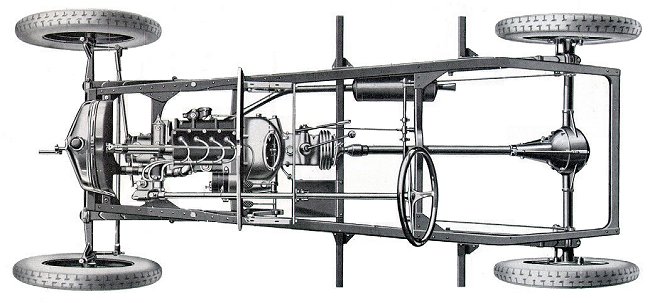
A rolling chassis consists of the frame, the wheels, the engine, the brakes, the transmission, the axles, the steering and the suspension.
The 7.5hp chassis is made from riveted cold pressed U-profiles of 3mm steel. To avoid torsions of the long profiles, a trapezoid shape was chosen.
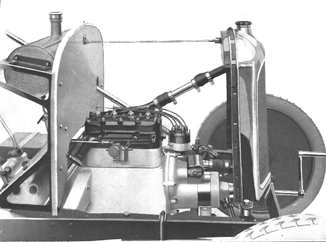
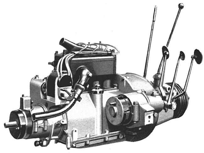
Engine, clutch and manual transmission form a single unit. This makes the whole unit more accessible and allows it to be attached to the frame in three places, which compensates for the deformation caused by the road. The engine is a four-cylinder with 55 mm bore and 90 mm stroke, which produces 11 hp at 2100 rpm. Oil mist is generated in the crankcase by means of splash lubrication, which ensures the lubrication of the engine. The thermosiphon principle is used for the cooling water circuit. The carburettor is a "SOLEX", of the type horizontal right. The fuel is supplied by gravity.
A single-disc dry-running coupling is provided. Three forward and one reverse gear are available for shifting gears. The reduction ratios are: 1st gear => i=0.316 (15,5 km/h), 2nd gear => i=0.562 (27,5 km/h), 3rd gear => i=1 (49 km/h), reverse gear: => i=0.246. The propeller shaft is inside a torque tube. The rotary motion is transmitted to the propeller shaft via a flexible fabric disc. The differential houses a pair of special herringbone bevel gears ("Chevrons Citroën") which provide power transmission to the rear drive axles. The steering system consists of a steering shaft with steering segment and is irreversible.
Four quarter elliptic are mounted on the chassis. The wheels are made of pressed sheet metal and are easy to remove as they are only attached to the hubs with four nuts. They were originally supplied to the assembly line with MICHELIN tyres, so for logistical reasons the standard colour black is used. Braking is achieved by two types of brakes, a differential brake located at the output of the gearbox and operated by a pedal, and a brake acting on the rear wheels and operated by a lever via a brake linkage.
The electrical 6V equipment of the chassis comprises a dynamo placed at the front end of the crankshaft and operated by the engine, a circuit-breaker contactor, an accumulator battery and an engine starter switch operated by a foot pedal.
Two kinds of chassis were manufactured:
| Chassis | Engine | Approx. production period | Approx. serial nr. |
|---|---|---|---|
| Type C2 (short chassis) | Battery ignition | March 1922 until September 1922 | 1 to approx. 5000 |
| Magneto | October 1922 until September 1923 | ca. 5000 to ca. 18000 | |
| Type C3 (long chassis) | Magneto | October 1923 until Mai 1926 | ca. 18000 bis 76000 |
Chassis Type C2
Official serial production started in march 1922 at the new factory at Levallois, specially
built for manufacturing the 7.5hp. It is nevertheless possible
that the very first cars had been assembled at the main factory at Quai de Javel.

Short while later the oil sump of the engine was equipped with cooling ribs, which replaced the initial oil pan without cooling ribs.
The serial number is stamped on the first approx. 3000 manufacturer's plates, later it is only stamped with punch numbers.
For production reasons from middle 1922 on the radiator was made from a radiator element and a separate nickel plated outer casing. The Citroën emblem on the radiator now has nickel-plated chevron arrows on a blue base.

The engine with battery ignition is equipped with the DELCO [L326] or R.B. DB4 system. The starter motor and dynamo are fixed by means of clamps.
Specifications:
| Frame | 4 traverses, rear open |
| Wheelbase | 2.25m |
| Ignition | battery (DELCO or R.B.) |
| Cut-out | on dynamo |
| Cylinder block | height 142.5mm |
| Flywheel | width 80mm |
| Differential | Round shape, herringbone gearing, ratio 9x44 |
| Number of spring leafs | front 5, rear 7 |
| Wheel dimension | 700x80 |
| Wheel studs spacing | 100mm |
| Steering | steering gear with short steering worm, Steering and track rod 1st version, steering wheel outer diameter 400mm. |
![[L108]](../../images/mod/Ankuend_Magneto.jpg "[L108]")
Period of production October 1922 until September 1923:
As the small additional sheet on the harvest 1922 catalogue shows [L108], the model 1923 was
equipped with a magneto ignition. The exact reason for this change is not documented in
any official bulletin.
It is generally assumed that the reliability of the battery ignition did not fulfil the expectations.
The designation of the magneto used is R.B. N 10 [L48].
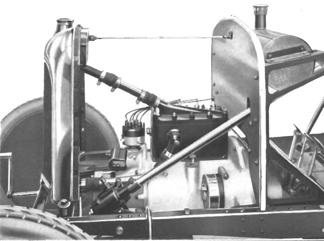
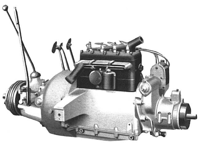
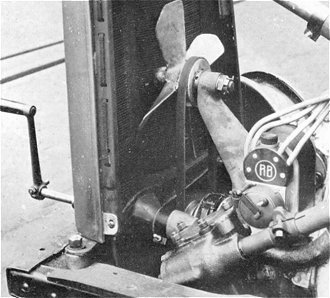
The starter motor is secured with a clamp (following figure (Picture 2-2) still with clamping piece). The dynamo front boss is equipped with a starting handle spigot for insertion of the starting handle The dynamo is equipped with a starting crank claw, so that this simplifies the starting crank system.
Specifications and modifications:
| Frame | 4 traverses, rear open |
| Wheelbase | 2.25m |
| Ignition | magneto (RB N 10/4) |
| Cardan shaft | 985mm |
| Number of spring leafs | front 5, rear 7 |
| Wheel dimension | 700x80 |
| Wheel studs spacing | 100mm |
Chassis Type C3
Period of production October 1923 until September 1926:
On the 1924 model the chassis frame was modified. The chassis became longer, was now over slung
over the rear axle and the rear section was closed off by a fifth chassis member.
The wheelbase was increased by 10cm to 2.35m.
This chassis frame was used until production end without major modifications.
By reducing the flywheel's inertia mass, the changing of gear was made easier enabling a more agile driving style.
From June 1924 all chassis were supplied with the newly introduced Michelin "Confort"
balloon tyres and the corresponding rims [L386].
From 1. June 1925 on, the cooling system was improved by a ventilator (from serial number
58517 on).
Specifications and modifications:
| Frame | 5 traverses, rear closed |
| Wheelbase | 2.35 m |
| Ignition | magneto (RB N 10/4) |
| Cardan shaft | 1085mm |
| Flywheel | width 56mm |
| Brakes | separate |
| Number of spring leafs | front 6, rear 8 |
| Wheel dimension | 700x80, from middle 1924 on 715x115 |
| Wheel studs spacing | 100mm |
| Steering | steering gear with long steering worm, Steering and track rod 2nd version, steering wheel outer diameter 410mm. |
Period of production October 1924 until May 1926:
The wheel studs spacing is increased to 130mm, which also entails a change in the spare wheel mountings.
The height of the cylinder block is reduced to 140.5mm [L146], which increases the compression [L79]. Cast steel pistons are replaced by cast aluminium pistons from engine no. 56160 [L39].
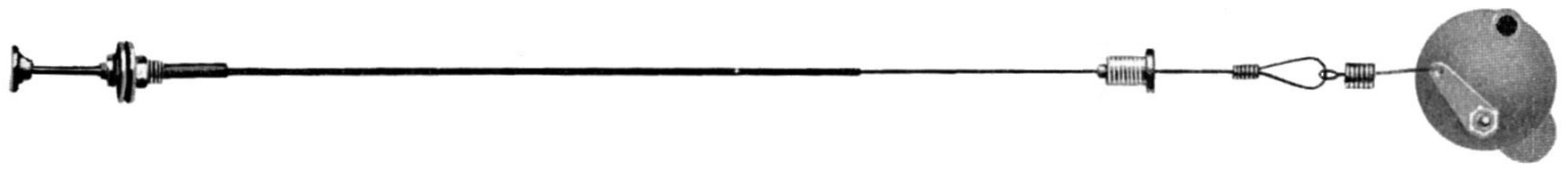
In January 1925 the SOLEX carburettor with barrel throttle slide was equipped with a choke [L146]. The carburettor with a valve throttle slide, which was used in July 1925, was also equipped with a choke [L146]. Both carburettors were fitted with a cable, which goes through the fixed bottom plate and has a choke lever on the dashboard. Old carburettors without air flaps can be retrofitted with a retrofit kit [L146].
The gearbox is reinforced [L146] by using an enlarged ball bearing at the front and a double-row ball bearing at the rear. This causes the connection of the brake drum to move backwards, which is compensated by a modification, which also affects the main shaft. The claws of the clutch shaft/direct gear are reinforced. The reduction ratios remain unchanged.
A cavity provided for collection of residues is at the bottom of the casing below the flywheel.The differential is revised [L146], with an oval differential housing, still using the proven herringbone gearing, but with a reduction ratio of 8x45.
Due to the low pressure «Comfort» tyres [L61], which exert higher forces on the steering gear, the steering segment and the steering worm were reinforced as well as the housing.
The cooling system was improved by a fan from June 1925 [L146] (serial no. 58517 [L39]) [L61].
Specifications and modifications:
| Frame | 5 traverses, rear closed |
| Wheelbase | 2.35 m |
| Ignition | magneto (RB N 10/4) |
| Cut-out | on motor wall. |
| Cylinder block | height 140.5mm |
| Flywheel | width 56mm |
| Cardan shaft | 930mm, without splined shaft end piece. |
| Differential | Oval shape, herringbone gearing, ratio 8x45 |
| Brakes | separate |
| Number of spring leafs | front 6, rear 8 |
| Wheel dimension | 715x115 |
| Wheel studs spacing | 130mm |
| Steering | Reinforced steering gear. |
Remark:
Differentials with helical gearing (Gleason) (9x44) for round rear axle housings were available as an alternative in the accessory market during the era [L145].
The differential housing is made of tempered cast iron and is equipped with a axial bearing to absorb the axial forces from the drive pinion.
The differential can be mounted without adjustments [L287].
However, such differentials were never equipped by the Citroën factory.
From 1928 on, only bevel gear pairs with helical gearing 9x50 for oval differential were available as spare parts.
To absorb the increased axial forces, the pinion bearing was modified and fitted with a double axial bearing.
Complete rear axles are available for both C2 and C3 chassis [L65, L218].